19.1 Connecting pin Removal and installation
Have questions or need a quote?
Get in touch with the team today.
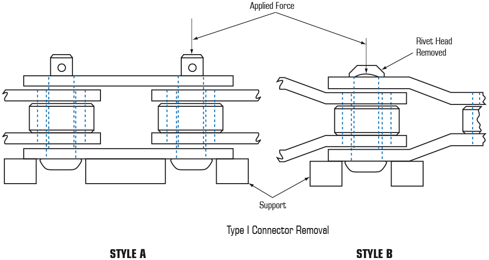
Correct removal is achieved by driving on the end opposite to the head and supporting the link as shown in fig. 19.1.1 The connector is in turn inserted by driving on the head of the connector and supporting the chain in a similar manner.
Split pin or solid cotter retention is typical of Engineering class and cast link chains. These should be removed before pin removal. In considering most chains the split pin or cotter should be cut flush with a sharp chisel or similar tool.
For chains of riveted construction, the most permanent fixing, but the least easy to remove, the riveted end should be ground flush prior to connector removal.
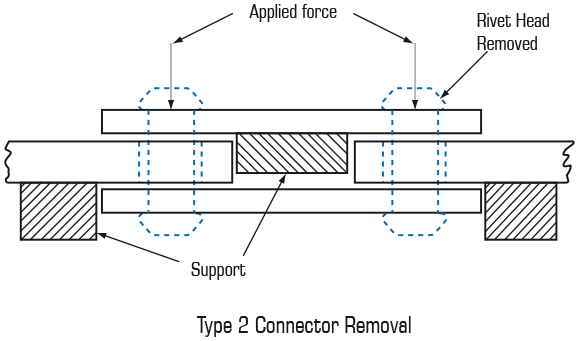
When disconnecting or connecting loose chain the chain must always be solidly supported against the floor or a solid work bench. When employing connectors shown in fig. 19.1 sufficient space should be created below the head (at least 2xHp sidebar thickness) to allow the connector to pass through the sidebar.
Type 2 connectors are typically found in hollow pin, draw bench and sideflex case chains. This style of connector has a shoulder or flat at both pin ends preventing the pin from travelling in a single direction. fig. 19.1.2 illustrates the preferred method of removal achieved by supporting the sidebar and pushing the ends of the connecting rivet free of the sidebar.